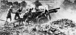
25-pdr Field Gun, Mount Etna 1943
|
|
Artillery design is a trade-off, with a shell usually being designed first, to be a certain weight and to be fired a certain range, and this then affects the design of the weapon firing it (especially the barrel). In the case of the 25-pdr, both a stopgap version and a completely new design were conceived almost at the same time. This was complicated by the low priority placed on the development of new weapon systems after the horrors of the First World War. The Royal Artillery Committee, in conjunction with the Director, Royal Artillery, headed the process. In 1924, the Committee was looking at the various options and a range of some 15,000 yards was considered appropriate. Various calibres and weights of projectile were considered, most notably 3.9in and 4.1in projectiles, the thinking being that two guns would be needed. The former would be fired from a quick-firing gun and the latter a breach-loading howitzer that would be able to reach 13,000 yards with a thirty-three pound projectile.
The process languished for several years until 1933 when a requirement was drawn up for a 3.7in gun / howitzer to fire a twenty to twenty-five pound projectile to replace the two previous designs. In 1934 a General Staff Specification was drawn up and models ordered for testing by the Director, Royal Artillery, Major General H A Lewis, including the prototype of the 25-pdr gun. Due to budgetary constraints at the time, the authorities looked at what was still around at the time - there being many 18-pdr guns in store - and looked to see if the old equipment could be modified to accept the new 25-pdr projectile. By 1935, a decision had been reached to refit the old 18-pdr jackets with 25-pdr ones and adapt the gun carriages with the fitting of pneumatic road wheels so that they could be towed by a vehicle. This rebored gun was to be fitted with the larger bore rifled liner and became the first of the 25-pdr series, the Ordnance QF 25-pdr Mk I. The relining of the barrel was possible because the 18-pdr barrel was made up of a number of parts:
The rifled bore, known as the 'A' tube could be removed and replaced by a larger bore liner of about 87.5mm calibre. This new tube was what is known as autofrettaged, that is, subjected to internal hydraulic pressure so that the metal on the inner surface of the bore is stretched beyond its elastic limit, while the metal towards the outside of the tube retains its elasticity. This leaves the barrel in a state of compression and is therefore much stronger. Such a technique is still used today. Despite this, the old 18-pdr carriages hampered performance and only 11,800 yards could be achieved in firing tests. It was obvious that further development of the gun carriage was required if it was to cope with the extra stress that the additional range would generate. This would be a problem as the 18-pdr had a pole trail, i.e. a single pole that attached to the limber, originating from directly under the breech. Such a configuration naturally had an impact on the gun's characteristics but later versions of the 18-pdr had already started to move towards the design that was eventually be used on the standard weapon. These were the split trail (the Mk VP) and one that had a box trail (the Mk III / IVP). As it was, around 1,000 of the Mk I design were converted and issued.
Both Vickers and the Royal Carriage Department (RCD) at Woolwich produced a split trail design, but the gunners, who would have to use it in action, were pretty unenthusiastic about either. The Vickers split trail was considered in 1937 but the box trail actually confers a number of advantages in the field, including the fact that the muzzle can be elevated to a higher angle as the breech can pass between the sides of the box trail. In actual fact, one can look at the 4.1in BL gun design (1931) to see the design roots of the Mk I 25-pdr gun carriage, which itself originated from a 1922 box trail design completed for the Spanish Government, also used for the Model 1922 105mm gun that became the basis for the BL gun and similar to the design on the 18-pdr Mk IV. Vickers apparently produced the gun for trials on Salisbury Plain and its clearly shows the humped box trail and firing platform. This carriage was fitted with the Mk II barrel (at the insistence of the gunners) and was the beginning of the 25-pdr as we know it today.
The Mk II was a very different weapon to the Mk I (also known as the 18 / 25-pdr) but was in development at about the same time the 18-pdrs were being converted to the new ammunition. The gunners were keen to see a weapon that would marry the advantages of being able to traverse 360 degrees with a box trail and so the final design started to take shape. The Royal Artillery Committee had specified the need for a circular platform in a memorandum dated 3 March 1926. Such a feature was found on the 4.1in BL gun, but an extemporised version had also been invented by Hogg and Paul and used in 1918, being based on a spare wheel but essentially performed the same function as the later all-steel version. The platform was a steel disc that had projections around its edge and was slung underneath the trail. If the gun went into action, the platform could be lowered and then pulled onto the platform by the tractor. Once there, one man with a handspike could rotate it in any direction, a feature that would become invaluable in the antitank role at a later date. Much of the production work was carried out at the Vickers plant in Newcastle (some 12,253 being built there) along with the relining of the 25-pdr Mk I barrel, although its plants in Sheffield and Scotland also contributed and the gun was eventually manufactured in both Canada and Australia during World War II.
As mentioned previously, the 25-pdr Mk I was not designed from scratch but a development of the old 18-pdr from World War I, with the barrel being a conversion of the Mk IV 18-pdr barrel to the new ammunition. While not a bad gun, it lacked the design features of the Mk II that would make that gun such a classic. The barrel consisted of an autofrettaged loose liner, jacket, breech ring, oil reservoir and screwed collar. At the end was a single-action Asbury breech (after its designer) that utilised a stepped, interrupted screw (known as the Welin pattern) to ensure the breech could be operated in one smooth movement. Brass cartridges ensured the breech was gas-tight as the gun was fired.
The carriages used with the Mk I barrel were known as the Mk IIITP, Mk IVP and Mk VP, the 'P' being used to denote the use of pneumatic tyres on the carriage. The first two were very similar; being box-trail (consisting of a crossbar, suspension frame, braking gear, cradle clamp, shield and traversing gear) in design while that latter was of a split-trail design. The gun could be transported at high speed due to the suspension frame insulating the trail and cradle from the shock, while the traversing gear allowed them to be moved 4.5 degrees to the right or left and could be worked from either side of the gun. The buffer recuperator worked the same way it did on the later Mk II with a buffer absorbing the recoil and a hydropneumatic recuperator returning the gun to its original position. The Mk VP could fire with an elevation of 15 degrees with the legs closed, or 37.5 degrees with them open, had a maximum depression of 5 degrees and was fired from the left-hand side. The carriage also allowed the gun to move left or right by 25 degrees, a big improvement over other marks. The axletree, trail legs and traverse were altered from the others marks by having the trail legs connected to the axletree and crossbar, with the axletree having two stub axles fitted and each trail leg having a metal ball bracket at the front. Two stop brackets that connected by a hook to two eyes on the stub axle limited the movement. The gunners sat on a seat mounted on the top of each leg. The carriage body rested on a bracket connected to the axletree and was made of manganese bronze and steel. The entire upper assembly (shield, gun and carriage body) traversed on the axletree and could be folded down whilst travelling.
The Mk II had a carriage that was designed to give 40 degrees of elevation and 5 degrees depression along with a traverse of 8 degrees. The barrel was mounted on a hydraulic buffer with a hydropneumatic recuperator that all worked within a cradle box that moved with the gun box after firing. The breech was a vertical sliding block with a mechanical firing lock. The Mk II had a variable charge system whereby propellant charges were loaded by inserting separate bags into the metal cartridge case and a primer inserted into the base. A shell was placed in the breech first, followed by the cartridge. The Mk II had two firing platforms associated with it, the No. 9 (for the Mk I carriage that was the larger of the two) and the No. 22 (for the Mk II and III carriages that were narrower). Both platforms had toe plates that dug into the ground and the gun could be towed onto the platform in seconds where it had a 360 degree movement. When the gun was on the platform, the trail spade was normally covered up in order to prevent it from digging into the ground and hinder the gun being traversed quickly. The Probert scale (named after an artillery officer who invented it) acted like a mechanical computer and expressed tangent elevation (the difference between the line of sight and elevation) as a range between 0 and 45 degrees engraved on the base of the cone. Range scales measured in hundreds of yards were also engraved on the cone and a muzzle velocity reader arm could also be read off against it. The gunners used a dial sight as the main indirect fire instrument that could be revolved between 0 and 360 degrees so that prominent features in the landscape could be viewed. The bearing between an aiming point and a target could be calculated and the gun offset from the aiming point by the same degree measurement called in by the observer. The were various versions of dial sights used, the most numerous being No. 7A, No. 7C and No. 9 and for direct aiming the No. 29 or No. 41 sighting telescope was used. A pair of aiming posts was used if there was a lack of prominent features.
There were several versions of the gun barrel. The original was the Mk I with a loose liner. The Mk II was the standard design and was also manufactured in Canada being known as the C Mk II and used at the same time during the early part of the war, being differentiated by the linear silhouette of the barrel showing a larger muzzle area. The Mk III was introduced in 1944 and had a modification to the chamber (the shot seating) to stop a round falling back if the barrel was elevated high enough. The Canadian version was known as C Mk III. The Mk IV saw a modification to the shape of the breech ring that was an attempt to stop it cracking when the gun was fired and the Mk VI was introduced in 1964 having a breech ring made out of better quality steel. The breech was operated by a lever on the right side of the gun, while the gun was fired by a lever operated through a mechanical linkage on the left-hand side. The gun barrel was mounted on a buffer / recuperator mechanism with the whole thing being contained within a cylinder block. The gun was mounted utilising two gun straps with the breech end being fitted with two thrust collars, themselves being connected to two cotters as part of the recoil system. The entire block recoiled with the gun inside the cradle and the pistons were fixed to the cradle front cap. The buffer dampened the effect of recoil and controlled the later stages of run-out while the recuperator helped with the recoil, controlled the run-out process and returned the gun to its normal position.
The carriages that were used with the Mk II and later barrels were the Mk I, Mk II and Mk III. The Mk I was a humped box trail design that had a firing platform and a front shield. The Mk II was a narrower design, for use in the jungle but the main design used was the Mk III that was similar to the Mk I but incorporated the smaller No. 22 firing platform. The trail sections on the rear quarter were jointed, so that when brackets on the gun trail were repositioned, the jointing mechanism could work, enabling the gun to be elevated up to 55 degrees (rather than having to dig a gun pit).
| Head: | Red - shell was filled Red crosses in a ring - a filled shell that was suitable for hot climates Black ring above Red ring - shell was fitted with exploders that were suitable for a powder-filled fuse White ring - Armour-Piercing round |
| Body: | Green band - Shell filled with Amatol or TNT Two Black bands - An HE Practice round One Black band - A drill shell (empty) Yellow band - A practice projectile |
No. 1 - the commander, made large traverses of the gun and normally positioned to the rear.
No. 2 - held the rammer, as well as operating the breech lever and stood to the right of the gun.
No. 3 - the 'Layer', sat on the wooden seat on the left-hand side of the gun, adjusted the sights, signalled adjustments to the No. 1 in big traverses and fired the gun.
No. 4 - the 'Loader'.
No. 5 - passed ammunition to the No. 4 and checked the fuses.
No. 6 - the second-in-command (2IC) who set the fuses and the charges, as well as being responsible for the movement and braking of the trailer.