|
|
 |
Many thanks to Paul Stahl Jr, for sending us this modification manual for the C-109 fuel transport, an modified verison of the B-24 bomber. His father, Paul Stahl Sr, was the project engineer for the C-109.
TEXT
Page 12 - Section 5 - Radio Modifications
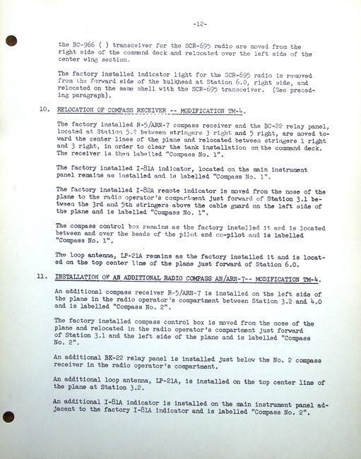
the BC-966 ( ) transceiver for the SCR-695 radio are moved from the right side of the command deck and relocated over the left side of the center wing section.
The factory installed indicator light for the SCR-695 radio is removed from the forward side of the bulkhead at Station 6.0, right side, and relocated on the same shell with the SCR-695 transceiver. (See preceding paragraph).
10. RELOCATION OF COMPASS RECEIVER - MODIFICATION TM-4
The factory installed R-5/ARN-7 compass receiver and the BC-22 relay panel located at Station 5.2 between stringers 3 right and 5 right, are moved towards the center lines of the plane and relocated between stringers 1 right and 3 right, in order to clear the tank installation on the command deck. The receiver is then labelled "Compass No.1".
The factory installed I-81A indicator, locataed on the main instrument panel remains as installed and is labelled "Compas No.1"
The factory installed I-82A remote indicator is moved from the nose of the plane to the radio operator's compartment just forward of Station 3.1 between the 3rd and 5th stringers above the cable guard on the left side of the plane and is labelled "Compass No.1"
The compass control box remains as the factory installed it and is located on the top center line of the plane just forward of Station 6.0
11. INSTALLATION OF AN ADDITIONAL RADIO COMPAS AN/ARN-7 -- MODIFICATION TM-4
An additional compass receiver R-5/ARN-7 is installed on the left side of the plane in the radio operator's compartment between Station 3.2 and 4.0 and is labelled "Compass No.".
The factory installed compass control box is moved from the nose of the plane and relocataed in the radio operator's compartment just forward of Station 3.1 and the left side of the plane and is labelled "Compass No.2"
An additional BK-22 relay panel is installed just below the No.2 compass receiver in the radio operator's compartment.
An additional loop antenna, LP-21A, is installed on the top center line of the plane at Station 3.2.
An additional I-81A indicator is installed on the main instrument panel adjacent to the factory I-81A indicator and is labelled "Compass No.2"