|
|
|
|
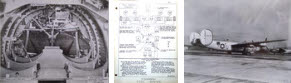
Many thanks to Paul Stahl Jr, for sending us this modification manual for the C-109 fuel transport, an modified verison of the B-24 bomber. His father, Paul Stahl Sr, was the project engineer for the C-109.
TEXT
Page 7 - Section 2 - Fuel System C-109 Airplane
FORWARD BOMB BAY TANKS (Cargo Tanks #2, #3)
These tanks have a capacity of 400 gallons each and are located in the forward bomb bay. They are installed in felt lined straps suspended from the bomb rails, and are droppable in flight. The provisions for installing these tanks are furnished by the factory in the form of a trunk or "Kit", whcih comes with the airplane as loose equipment.
Both the vent and outlet connections on these tansk run through "Hallett" type quick disconnect fittings with check valves for dropping purposes. The vent is connected to the top skin of the airplane by means of a 3/4" rubber tube. The outlet connections consist of 1" O.D. tubing running to selector valves on the forward defueling manifold on the catwalk in the aft bomb bay.
The filler caps are located on the top aft inboard end of each tank and are accessible from the ground when the forward bomb bays are open.
AFT BOMB BAY TANKS (Cargo Tanks #4, #5)
The installation of the aft bomb bay tanks is essentially the same as the forward bomb bay installation except that the droppable mechanism differs in detail and the capacity of the aft tanks is approximately 425 gallons each. The outlet and vent connections are the same. The filler caps are located on the top aft inboard and of each tank and are accessible for filling from the ground when the rear bomb bay doors are open.
DECK TANKS (Cargo Tanks #6, #7, #8)
These tanks are located on the command deck and are installed in felt lined wooden cradles which are fastened rigidly to the structure of the airplane. The number 7 tank is located "crosswise" the command deck and adjacent to the rear spar of the wing center section. Tanks #6 and #8 are left-hand and right-hand tanks located "lengthwise" on either side of the command deck. They are all held in the cradles with felt lined metal straps using turn-buckles for adjustment.
The outlet or defueling lines run from a fitting on the bottom of each tank to a header clamped to the bulkhead at Station 6.0. The three outlet lines join at this point and a single 1-1/4" line runs from this header to the mainfold located on the catwalk in the aft end of the rear bomb bay. A 3/4" rubber hose vent line runs from the top of each tank to individual fittings riveted to the top skin of the airplane.
A filler cap is locataed on top of each tank and to fill these tanks it is necessary to bring a filler hose in through the rear bomb bay or through the waist windows of the airplane.