Consolidated C-109 Gallery
|
|
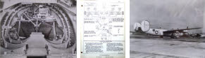
| C-109 Modification Manual - p.6 Fuel System |
Many thanks to Paul Stahl Jr, for sending us this modification manual for the C-109 fuel transport, an modified verison of the B-24 bomber. His father, Paul Stahl Sr, was the project engineer for the C-109.
TEXT
Page 6 - Section 2 - Fuel System C-109 Airplane
GENERAL
The cargo system of the C-109 Airplane consists of a series of aluminun alloy fuel tanks distributed in the airplane as follows:
TANK NO. LOCATION CAPACITY 1 Nose Compartment 100 Gallons 2 & 3 Fwd. Bomb Bay 400 Gallons Ea. 4 & 5 Aft Bomb Bay 425 Gallons Ea. 7 Fwd Command Deck 120 Gallons 6 & 8 Side Command Deck 180 Gallons Ea *Total Cargo Capacity 2,230 Gallons *Not including outboard auxiliary fuel cells in wings, which may be used for cargo also The above tanks are interconnected by a system of piping which terminates at defueling manifolds located on the catwalk in the aft bomb bay.
A tee connection into an electric fuel transfer pump, located on the catwalk in the forward bomb bay, makes in possible to transfer gasoline in the cargo tanks into the main fuel system of the airplane, thus making this extra gasoline available in flight. A portable gasoline driven defueling pump and 30 feet of hose are stowed in the airplane. This defueling unit is used to pump out the cargo tanks by connected it to the outlet fittings provided on each of the two defueling manifolds. Selector valves on each manifold allow individual tanks to be emptied. These valves are accessible from outside the airplane by opening the rear bomb bay doors. The individual tank installations are as follows:
NOSE TANK (Cargo Tank #1)
This tank has a capacity of 100 gallons (not including expansion space) and is located in the bombardier's compartment. It is installed in a felt lined wooden cradle, which is attached rigidly to the structure of the airplane. The tank is held in the cradle with felt lined metal straps using turnbuckles for adjustment. This tank is not droppable.
The filler cap is located on the top aft end of the tank and is accessible for filling through the nose wheel opening. A 3/4" vent connection is on the forward end of the tank and is connected to a vent flange, riveted to the upper skin of the nose, by a 3/4" rubber hose. A welded "Y" fitting is provided in the vent line adjacent to the tank for the CO2 purging line connection. The outlet or defueling connection consists of a 1" O.D. tube running from a flange on the bottom of the tank directly to the forward defueling manifold on the catwalk in the aft bomb bay.