|
|
|
|
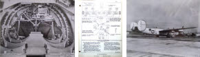
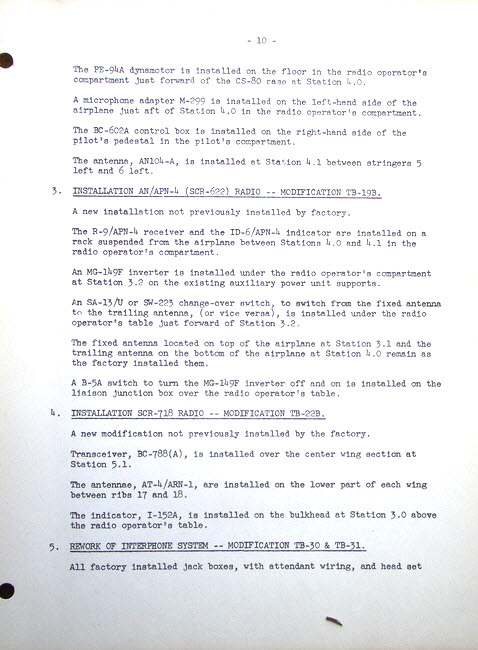
Many thanks to Paul Stahl Jr, for sending us this modification manual for the C-109 fuel transport, an modified verison of the B-24 bomber. His father, Paul Stahl Sr, was the project engineer for the C-109.
TEXT
Page 10 - Section 5 - Radio Modifications
The PE-94A dynamotor is installed on the floor in the radio operator's compartment just forward of the CS-80 case at Station 4.0
A microphone adaptor M-299 is installed on the left-hand side of the airplane just aft of Station 4.0 in the radio operator's compartment.
The BC-602A control box is installed on the right-hand side of the pilot's pedestal in the pilot's compartment.
The antenna, AN104-A, is installed at Station 4.1 between stringers 5 left and 6 left.
3. INSTALLATION AN/APN-4 (SCR-622) RADIO -- MODIFICATION TB-19B
A new installation not previously installed by factory
The R-9/APN-4 receiver and the ID-6/APN-4 indicator are installed on a rack suspended from the airplane between Station 4.0 and 4.1 in the radio operator's compartment.
An MG-149F inverter is installed under the radio operator's compartment at Station 3.2 on the existing auxiliary power unit supports.
An SA-13/U or SW-223 change-over switch, to switch from the fixed antenna to the trailing antenna, (or vice versa), is installed under the radio operator's table just forward of Station 3.2
The fixed antenna located on top of the airplane at Station 3.1 and the trailing antenna on the bottom of the aircraft at Station 4.0 remain as the factory installed them.
A B-5A switch to turn the MG-149F inverter off and on is installed on the liaison junction box over the radio operator's table.
4. INSTALLATION SCR-718 RADIO - MODIFICATION TB-22B
A new modification not previously installed by the factory
Transceiver, BC-788(A), is installed over the center wing section at Station 5.1
The antennae, AT-4/ARN-1, are installed on the lower part of the each wing between ribs 17 and 18
The indicator, I-152A, is installed on the bulkhead at Station 3.0 above the radio operator's table.
5. REWORK OF INTERPHONE SYSTEM - MODIFICATION TB-30 & TB-31
All factory installed jack boxes, with attendant wiring, and head set